
Hand tools with custom pockets
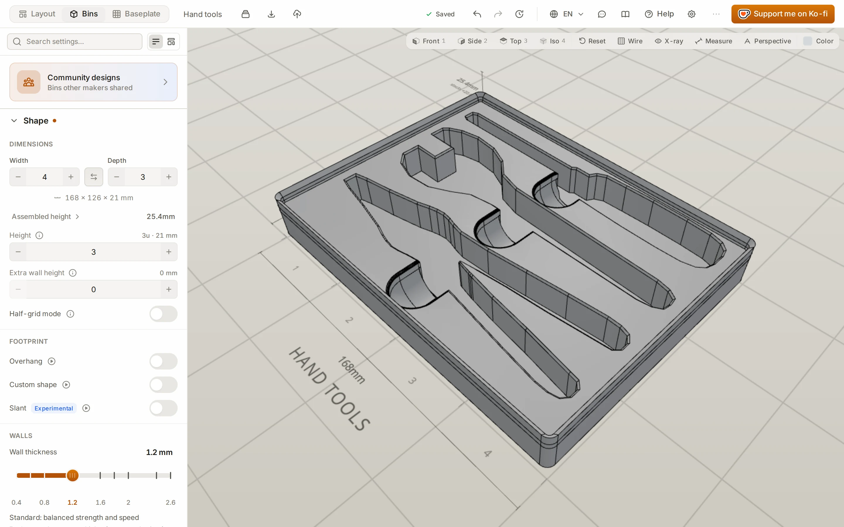
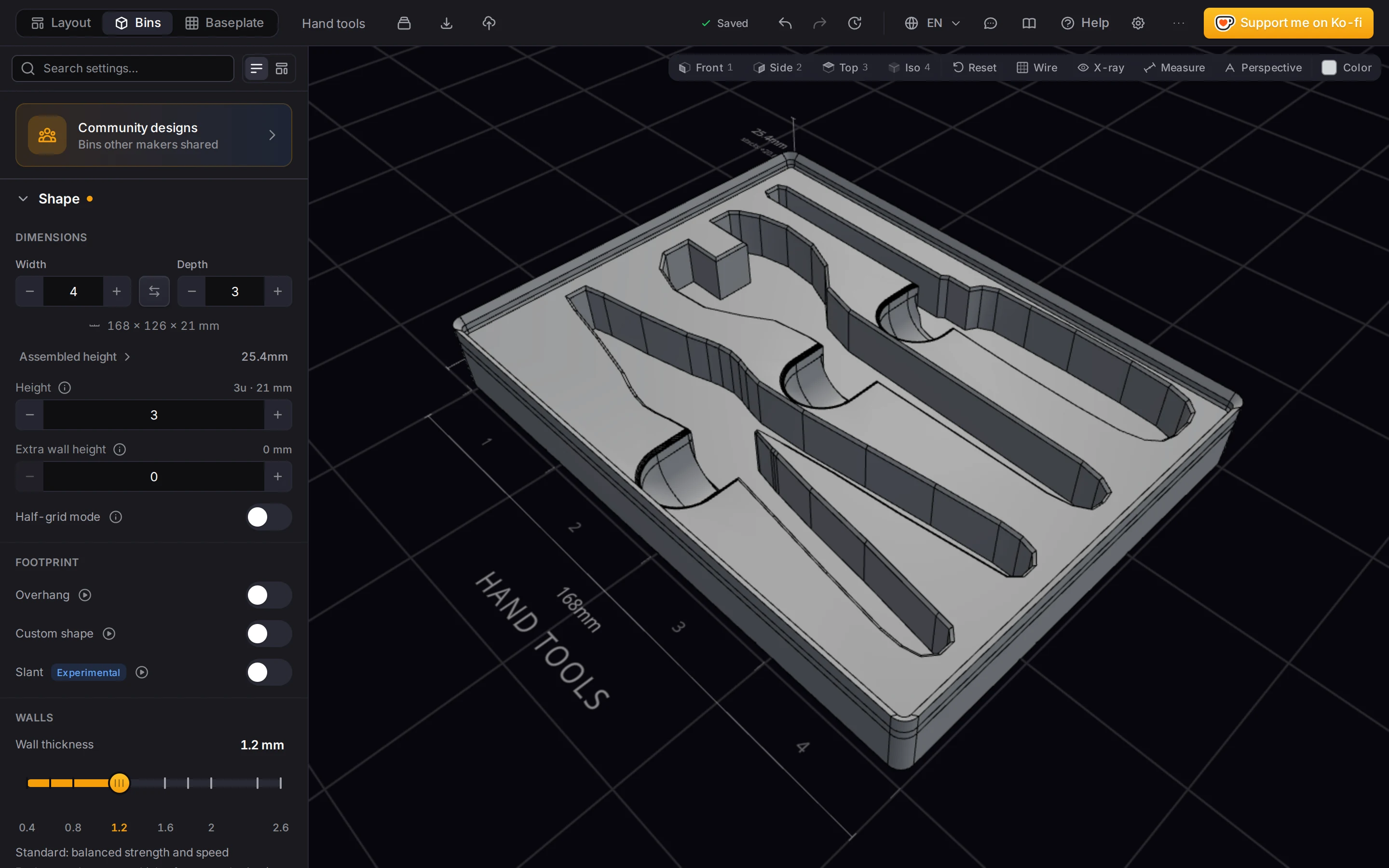
A pocket shaped like each tool shows at a glance which tool is out of the drawer. In this recipe, you photograph three hand tools with your phone, and the bin designer cuts a pocket for each one. You add a finger scoop to lift each tool out, and you print a thin test before the full bin.
What you need
- The tools. This recipe uses pliers, an adjustable wrench and a screwdriver, each shorter than 160 mm.
- A phone with a browser, and a size reference. A plain sheet of A4 or US Letter paper works. The printed calibration sheet works best.
- Calipers or a ruler, to measure the thickest part of each tool.
- A print bed of 168 mm or more. The bin is 4 × 3 grid units, or 168 × 126 mm.
For the filament, read the export window in the bin designer. It counts the solid bin. The bin list in the layout editor counts a hollow bin, so it reads low for this one.
Step 1: Start a solid bin
- Open the bin designer, and set the size to 4 × 3 grid units, 3u tall.
- In the Interior group, pick Custom cutouts.
The bin is now a solid block, and the pockets cut down into its top. Inside its 1.2 mm walls, the top is 165.1 × 123.1 mm. That's 4 × 42 mm less 0.5 mm of fit gap and two walls, by 3 × 42 mm less the same.
Not sure of the size? Lay the tools side by side with a finger's width between them, and measure the space they take. Round up to whole grid units of 42 mm.
Step 2: Scan the tools with your phone
- Click Scan a tool, then With your phone.
- Point the phone camera at the QR code and open the link. The link lasts 10 minutes, so lay out the tools and the reference first.
- Put the tools on a plain sheet of A4 or US Letter paper with a gap between them. Use a table darker than the paper, and keep all four corners of the sheet in the photo.
- Tap Take a photo, and hold the phone level, straight above the tools. Hold it high, and zoom in until the sheet fills the photo.
- Check each outline in the review, and tap Use this outline.
The tools land in the bin as one group. Each pocket already has 0.4 mm of clearance and a chamfer at its top edge, so the tool drops in. Scan with your phone covers the size references and the review screen.
TIP
No phone? Click Scan a tool and trace a photo from your computer instead, as in Trace a photo. Or draw the pockets yourself with the Slot and Pen tools.
Step 3: Set the pocket depth
The bin designer now asks how thick the tools are. Measure the thickest part of each tool.
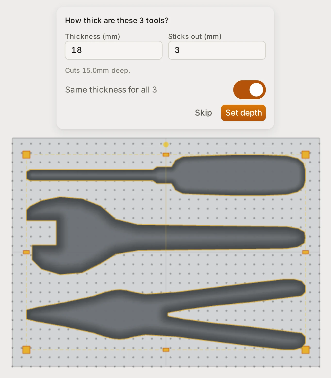
Say the pliers are 18 mm thick. Type 18 in Thickness (mm). A 3u bin has room for 16.25 mm: 21 mm of bin, less 4.75 mm of feet. So the prompt warns you and offers to make the bin 4u tall. You have two good choices:
| Choice | Result |
|---|---|
| Make the bin 4u tall | The tool sits flush. A 4u bin has room for 23.25 mm. |
| Type 3 in Sticks out (mm), and keep 3u | The pocket is 15 mm deep, and the tool stands 3 mm proud for a good grip. |
Then click Set depth. To give each tool its own depth, turn off the switch that sets the same thickness for all.
Step 4: Add finger access and arrange
A snug pocket holds a tool well, but you need a way to get a fingertip under it.
- A click on the board selects the whole group. To select one tool, click its row in the Shapes tab.
- In the Properties tab, open Shape and click Add finger access.
- Do the same for each tool.
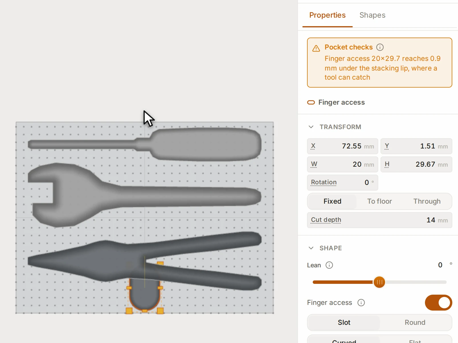
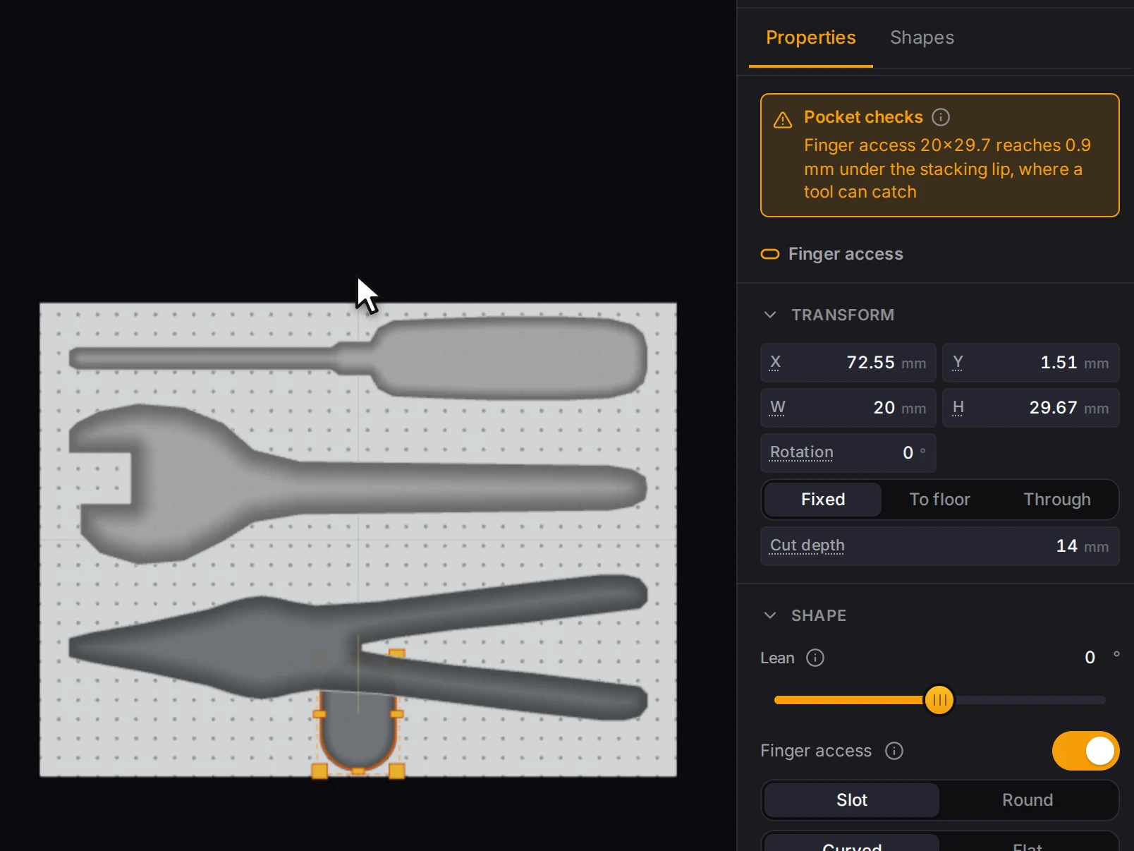
Each scoop is 20 mm wide, at the middle of a long side of the tool. It goes on the side toward the front of the bin when that side has room. The scoop reaches 20 mm out from the tool. It also reaches up to 20 mm back over the tool, but it stops before the far edge of the pocket. So a narrow part of a tool gets a shorter scoop.
Drag the group to place the tools in the bin. If a tool hangs past the edge, a warning offers a button that makes the bin larger. Arrange cutouts shows how to align and pack them.
When a pocket has a problem, a Pocket checks box shows at the top of the Properties tab. The box flags any spot with less than 1.2 mm of plastic, for example between two pockets. It also tells you when a scoop reaches under the stacking lip, where a tool can catch. Check before you print shows how to clear that warning.
No box means that the checks found no problem. The checks measure at the top surface only, so two pockets that lean toward each other can still meet lower down. Turn the 3D preview to look at them before you print.
Step 5: Print a fit test first
A full solid bin is a long print. A test ring takes a fraction of the filament.
- In the Properties tab, click Print fit test.
- Pick Outline only. Each pocket becomes a thin ring, 0.6 mm tall and 1.2 mm wide, whose inside edge is the pocket wall.
- Export the file and print it flat.
- Lay each tool in its ring.
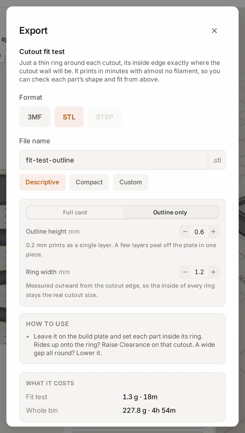
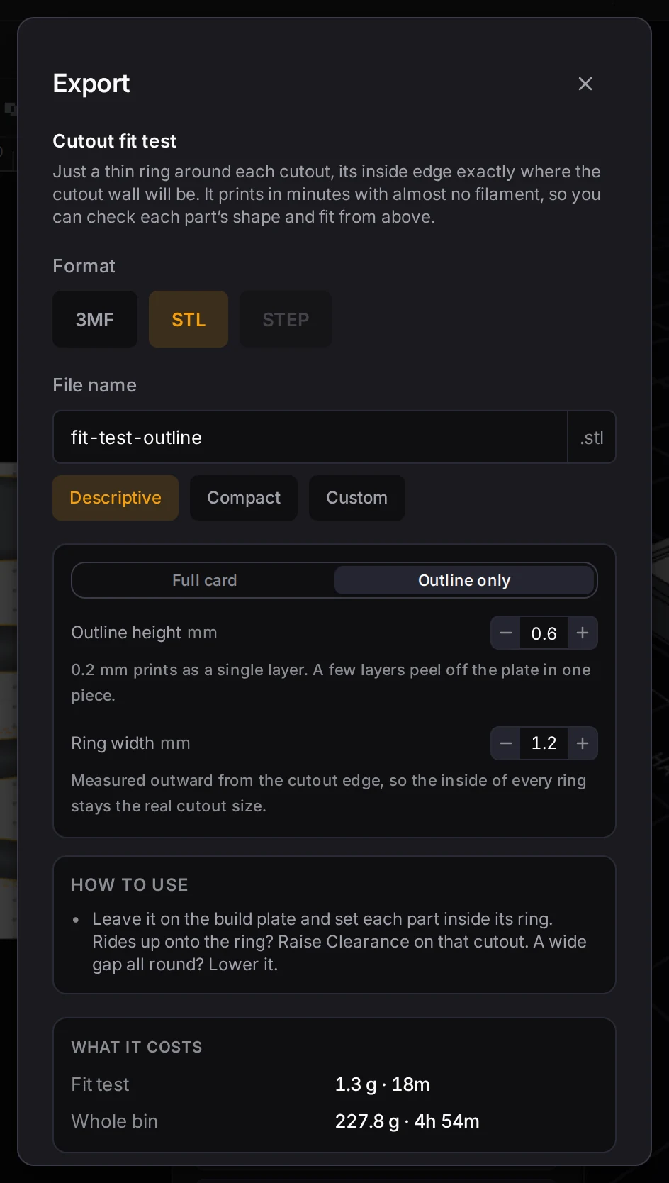
The window also compares the filament and the time of the test with the whole bin. When every tool drops in with a small, even gap, export the bin with Export. To put it in a drawer, use Place in layout in Saved designs.
When it goes wrong
A tool is too tight, or it rattles
Select that pocket and open Fit & insertion. Make Clearance larger for a tight tool, or smaller for a loose one. Scans start at 0.4 mm. Print a new ring before the bin. Fit and tolerances helps you find the value that suits your printer.
A tool is hard to lift out
Add finger access to that pocket if it has none. You can also set Entry edge to Round, a smooth curve for tools that you lift by hand. Or let the tool stick out a few millimeters, as in step 3.
The pocket is the wrong size
Plain paper and a bank card measure less exactly than the printed calibration sheet. Print the sheet at 100% and check that its bar is 100 mm. For a tall tool, lay a measuring strip on top of it, because the top of a tall tool looks larger to the camera. Compare the size in the phone review with a ruler before you tap Use this outline. See Scan with your phone.
Next steps
- Check before you print: every pocket warning, and the full-card fit test
- Cutout basics: depth modes, two-depth pockets and wall openings
- Arrange cutouts: repeats, groups and labels for each pocket
- Swappable label plates: a label plate beside each tool