
The base
The base is the underside of a bin: the feet that lock into a baseplate, the holes for magnets and screws, and the floor. Add magnets to the bins and the baseplate, and your bins snap onto the plate instead of sliding around. Hollow the feet, and the bin uses less filament. Anatomy of a bin explains how the feet sit in a baseplate.
In the bin designer of the Gridfinity Layout Tool, open the Base group. Below the Body type tiles and the stacking lip controls, the base controls sit in three sections:
- Mounting: magnet and screw holes.
- Feet: half-size feet, the foot lattice and detachable feet.
- Floor: the lightweight floor.
When a body type cannot have a section, the section shows one line that tells you why.
Add magnet holes
- Under Mounting, turn on Magnet holes.
- Click Customize to show the hole settings.
- Set Magnet diameter to the diameter of your magnets.
- Set Magnet depth to the thickness of your magnets.
The diameter goes from 4 to 10 mm, with a default of 6.5 mm. The depth goes from 1 to 4 mm, with a default of 2 mm. Not sure? Keep the defaults. They suit a standard 6 by 2 mm magnet.
Hold magnets without glue
Glue is messy. Two options in the same Customize fold help a magnet stay in its hole without it, and you can use both together.
| Option | What it does |
|---|---|
| Crush ribs | Eight ridges in each hole crush when you press the magnet in, so it holds without glue. |
| Chamfered mouth | A 45° lead-in at the opening of each hole guides the magnet in straight. |
A lightweight floor and a Nesting body leave too little material around each hole for Chamfered mouth.
Add screw holes
Turn on Screw holes and set Screw diameter, from 2 to 6 mm. The default is 3 mm. A bin can have magnet holes and screw holes together.
Put holes at the corners only
By default, every foot gets its holes. Turn on Corners only to put the holes only at the outer corners of the bin. A large bin then needs fewer magnets and lifts off the baseplate more easily.
A half-size foot keeps the holes it has space for: two along its long side, or one in its center.
INFO
Three body types cannot have magnet or screw holes:
- Flat base
- Lid base
- Spacer
A Nesting body takes magnets but no screws, and places its magnets itself. See Stacking.
Use half-size feet
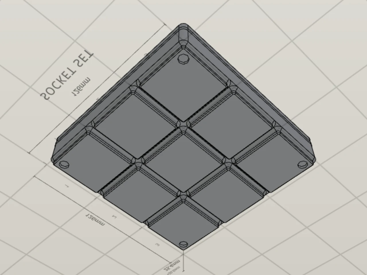
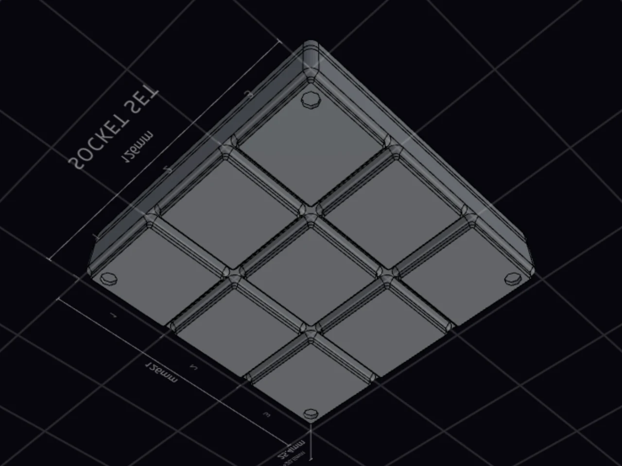
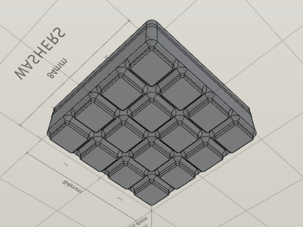
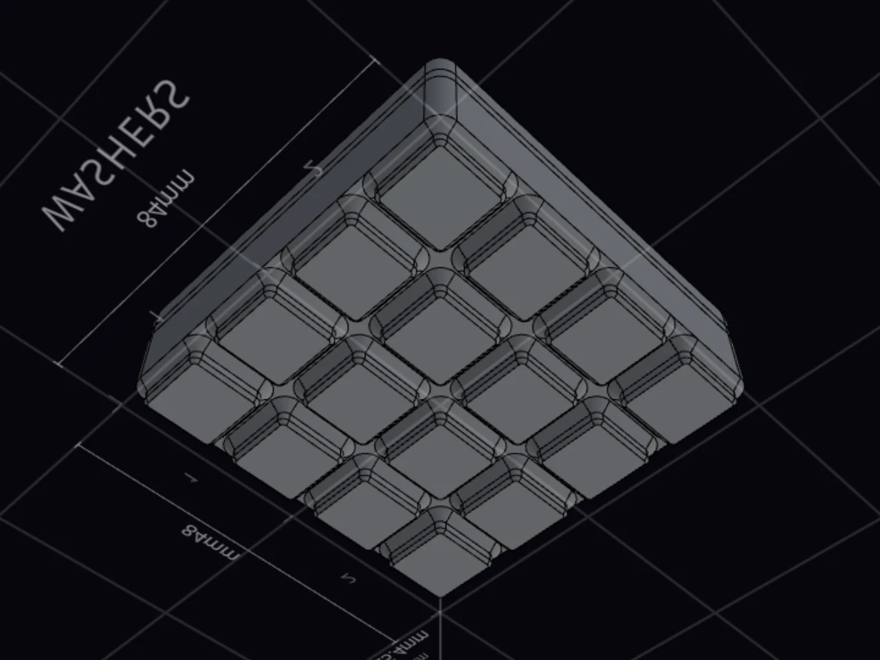
Turn on Half sockets under Feet to split each foot into feet half a grid unit wide. These feet seat in a baseplate at either half-unit offset.
Set the foot lattice
A foot must land inside one pocket of the baseplate. A full foot on the edge of a pocket doesn't drop in. The Foot lattice fold sets where the feet fall on each axis:
- On grid: use it when the edge of the bin is on a grid line. This is the default.
- Half offset: use it on an axis where the bin sits half a unit off the grid.
Half sockets, a custom shape and a half-unit size keep the lattice on grid.
Print detachable feet
Detachable feet prints the bin with a flat bottom and pin holes in the floor. The feet print as separate parts, and you press them on by hand. Wear one out? Print a new foot and swap it.
- Turn on Detachable feet.
- Pick a Pin size, from ø2.6 to ø3.2 mm. The default is ø2.8 mm.
- Drag the slider in the 3D preview to drop the feet off the bin and look at the joint.
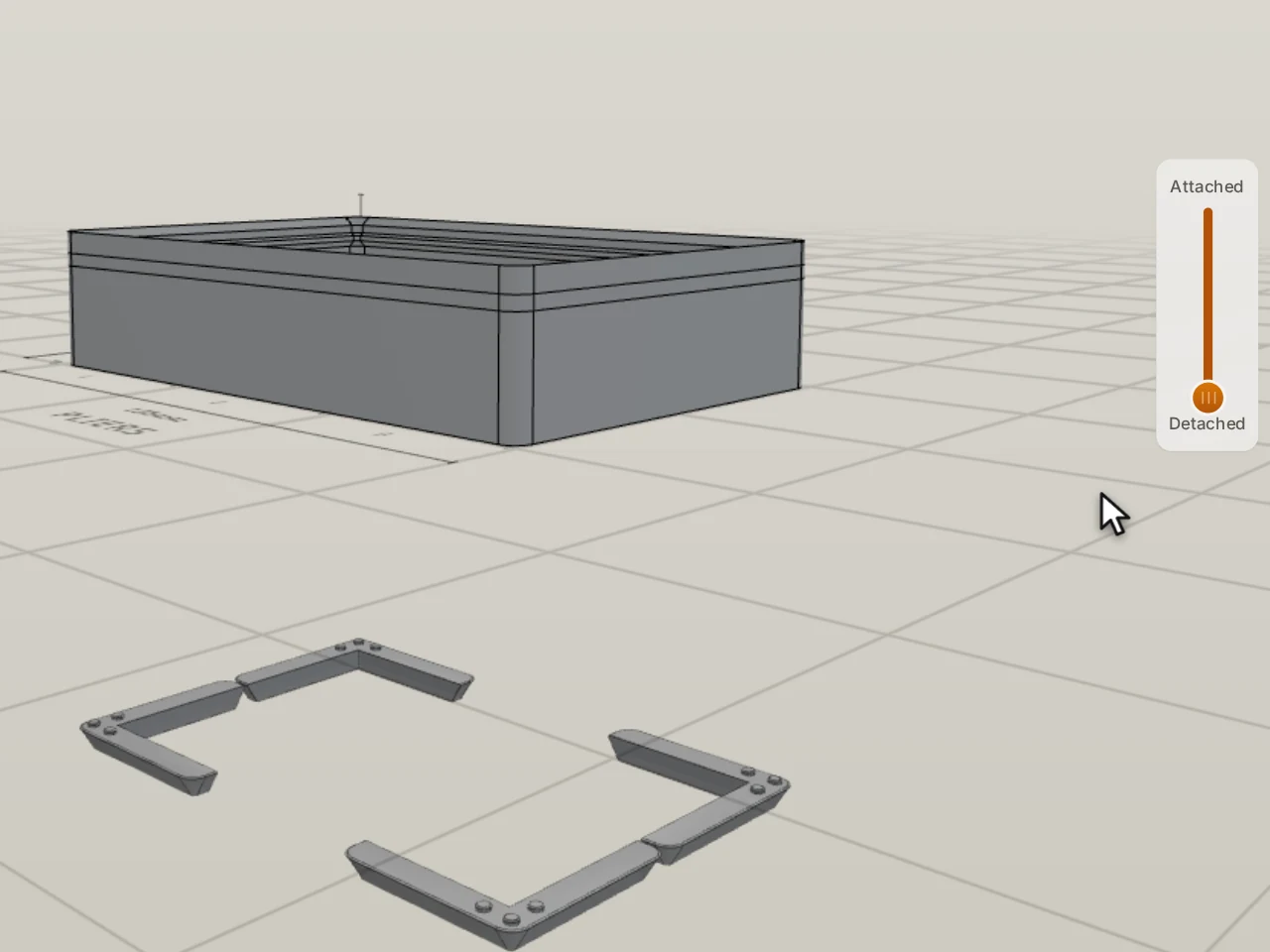
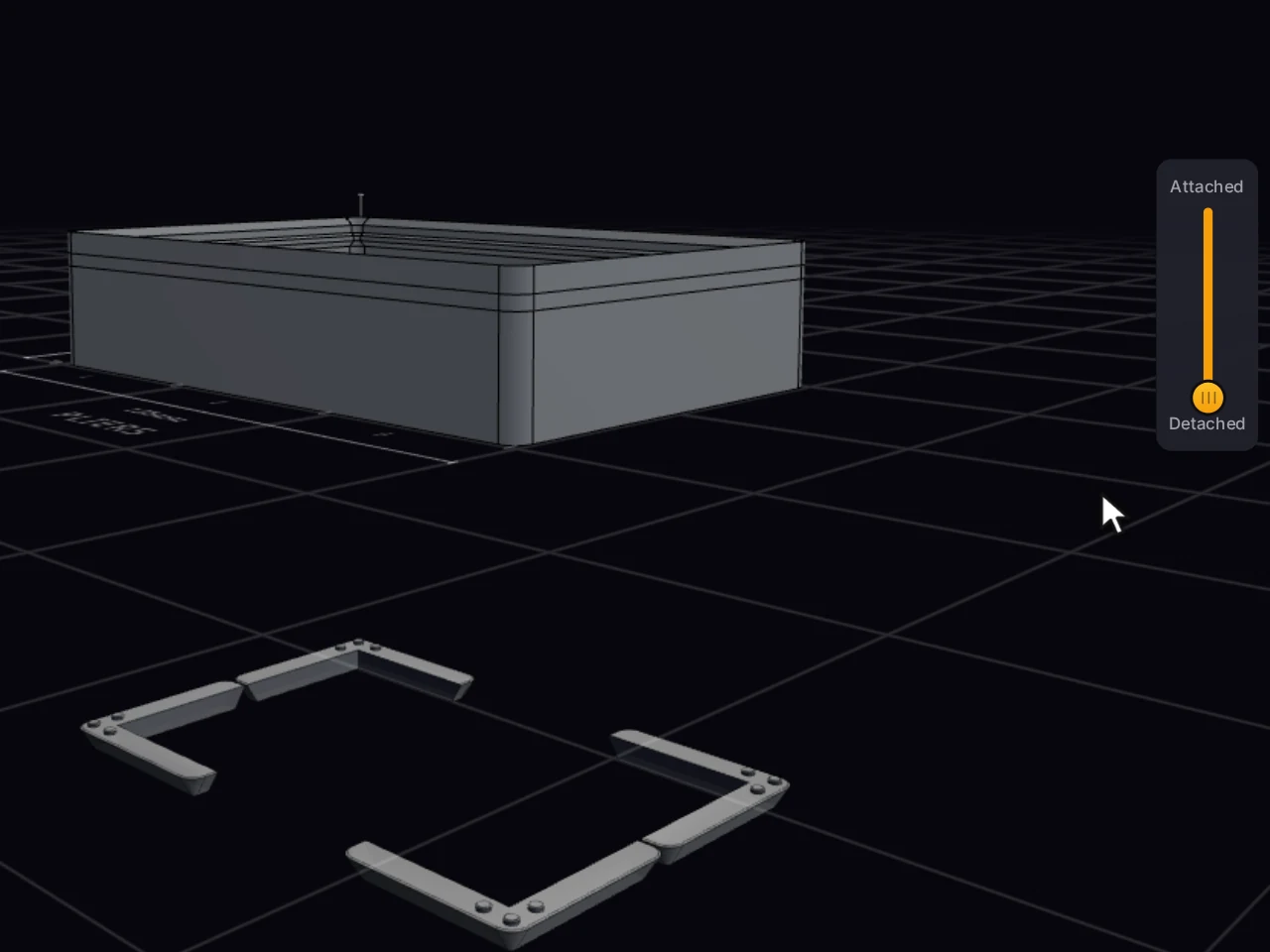
The pin holes are 3 mm wide. If a foot won't go on, pick a smaller pin. If a foot comes loose, pick a larger pin.
The feet go at the outer whole cells, never under the middle of the floor. The bin designer adds feet where the gap between two feet is more than 140 mm. The panel shows how much material the bin saves.
WARNING
Use a wall of 1 mm or thicker for detachable feet. A thinner wall leaves too little floor to hold a pin, so you cannot turn on the toggle.
With detachable feet on, these options have no effect:
- Half sockets
- Lightweight floor
- Feet under overhang
A spacer needs its built-in feet to hold together, so it cannot have detachable feet.
Make the floor lighter
Want to save filament on a big batch? Lightweight floor under Floor hollows each foot. Click Customize under it to pick Lightweight mode, the side it opens from:
| Mode | Result |
|---|---|
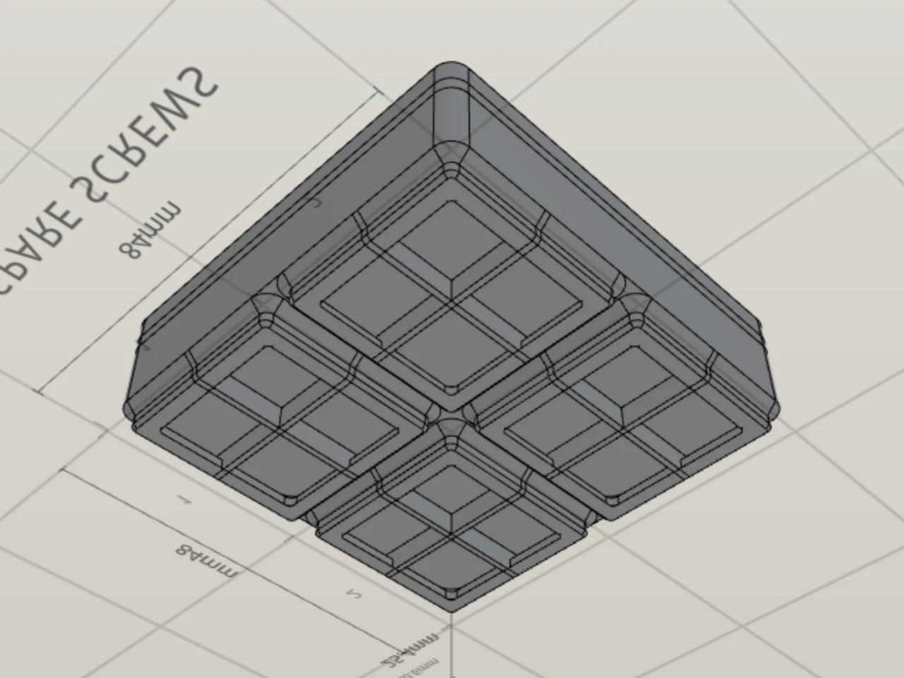
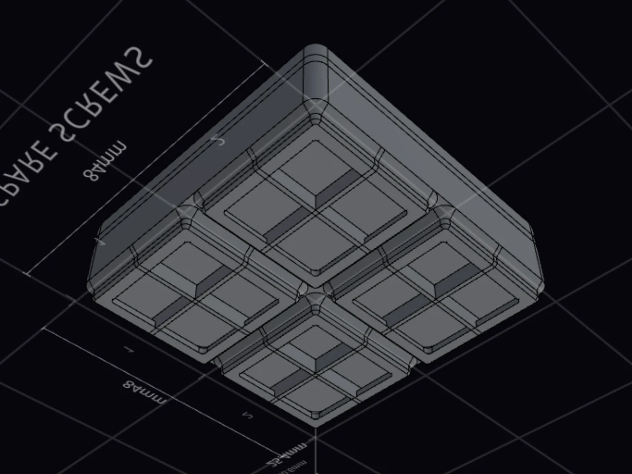
| Inside | Each foot is hollow from the inside, and the grid shape shows in the floor. It saves the most filament. |
| Underside | Each foot is hollow from below, and the floor of the bin stays flat. |
Small or flat items can fall into the recesses of the Inside mode. That mode also removes the solid floor that a finger scoop, an interior fillet, cutouts and drainage holes need.
Hollow the floor from underneath
Pick Underside to keep a flat floor inside the bin. If you're not sure which mode to use, this is the safer pick. Each foot becomes a ring with a 3 mm wall, and the floor of the bin closes it at the top. Finger scoops and drainage holes still work.
When another feature blocks the lightweight floor, the panel can show Use underside relief. Click it to turn on the floor in the underside mode, which works with that feature.
A spacer cannot have a lightweight floor. A Base only bin can use only the underside mode.
Use a low-profile base
Low-profile base is an option of the layout in the baseplate generator. It gives every bin in the drawer 1.1 mm more space inside at the same height. The feet are 1.1 mm shorter, and the floor is 1.1 mm lower.
When the layout uses it, the Feet section shows a note. Standard Gridfinity bins still sit in a low-profile plate, with less grip. A design that you share or publish always gets standard feet, because the low-profile setting belongs to your layout, not to the design.
Make a bin without sockets
A Flat base has no Gridfinity feet, so the bin sits flat on any surface and doesn't lock into a baseplate. Use it for a shelf or a desk. A Lid base also has no feet, because its underside is a lid.
These two body types cannot have magnet or screw holes, half sockets, a lightweight floor or detachable feet. Drainage holes still work on a flat base.
For all six body types, see Pick a body type. For imported bins and Workshop builds, see Other bin types.
When it goes wrong
A banner says the bin won't drop into a baseplate
Click Match layout in the banner. The bin designer sets the foot lattice to match where the bin sits in your drawer.
The bin sits half a unit off the grid in the layout, but its feet follow the grid. The feet then land on the ridges between the pockets. See Set the foot lattice.
A big bin is hard to lift off the baseplate
Turn on Corners only under Mounting, and print the bin again. It then takes magnets at its outer corners only.
Each magnet adds grip, and by default every foot gets its holes. A large bin with magnets under every foot holds very firmly.
Magnets fall out of their holes
Turn on Crush ribs in the Customize fold of the magnet holes. Print the bin again, and press the magnets in.
A plain round hole holds a magnet only when its size suits your printer exactly. The ribs crush as the magnet goes in, so it holds without glue. See Fit and tolerances.
A detachable foot won't go on, or it comes loose
Pick a smaller Pin size if a foot won't go on. Pick a larger one if a foot comes loose. Then print the bin and the feet again.
The pin hole in the bin is always 3 mm wide. Each printer prints a small pin a little larger or smaller than its model, so the pin size lets you match your printer. On most bins, the pin size also moves some pins a little, and the holes in the bin move with them. So new feet line up only with a bin that you print at the same pin size.
Next steps
- Stacking: set the stacking lip on top of the bin.
- Walls: add drainage holes to the floor.
- Magnets and screws: match the holes in the baseplate.
- Fit and tolerances: tune the fit of magnets and pins.