
Cutout basics
Give every tool its own spot. A cutout is a pocket shaped like a tool, which the Gridfinity Layout Tool cuts into the top of a solid bin. Draw one here, then set its size, depth, edges and label.
Open the cutout editor
- Open the bin designer.
- In the Interior group, select Custom cutouts.
- Click Cut editor.
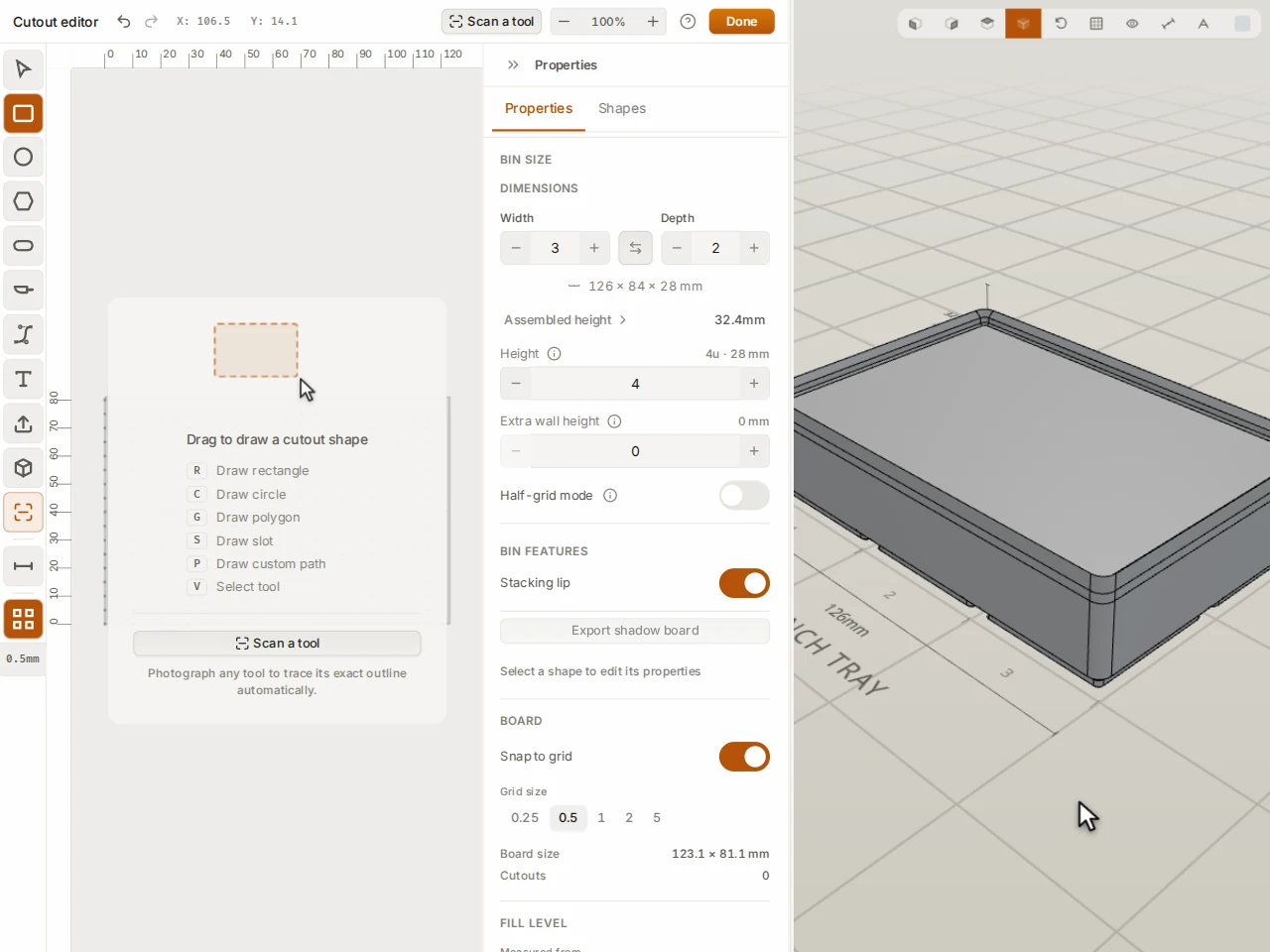
The Cutout editor opens beside the 3D preview. The panel on the right has two tabs: Properties and Shapes. When you finish, click Done to close the editor.
INFO
The editor needs a desktop screen. On a phone or a tablet, you can scan a tool into the bin, but you move and change the cutouts on a computer.
Draw a cutout
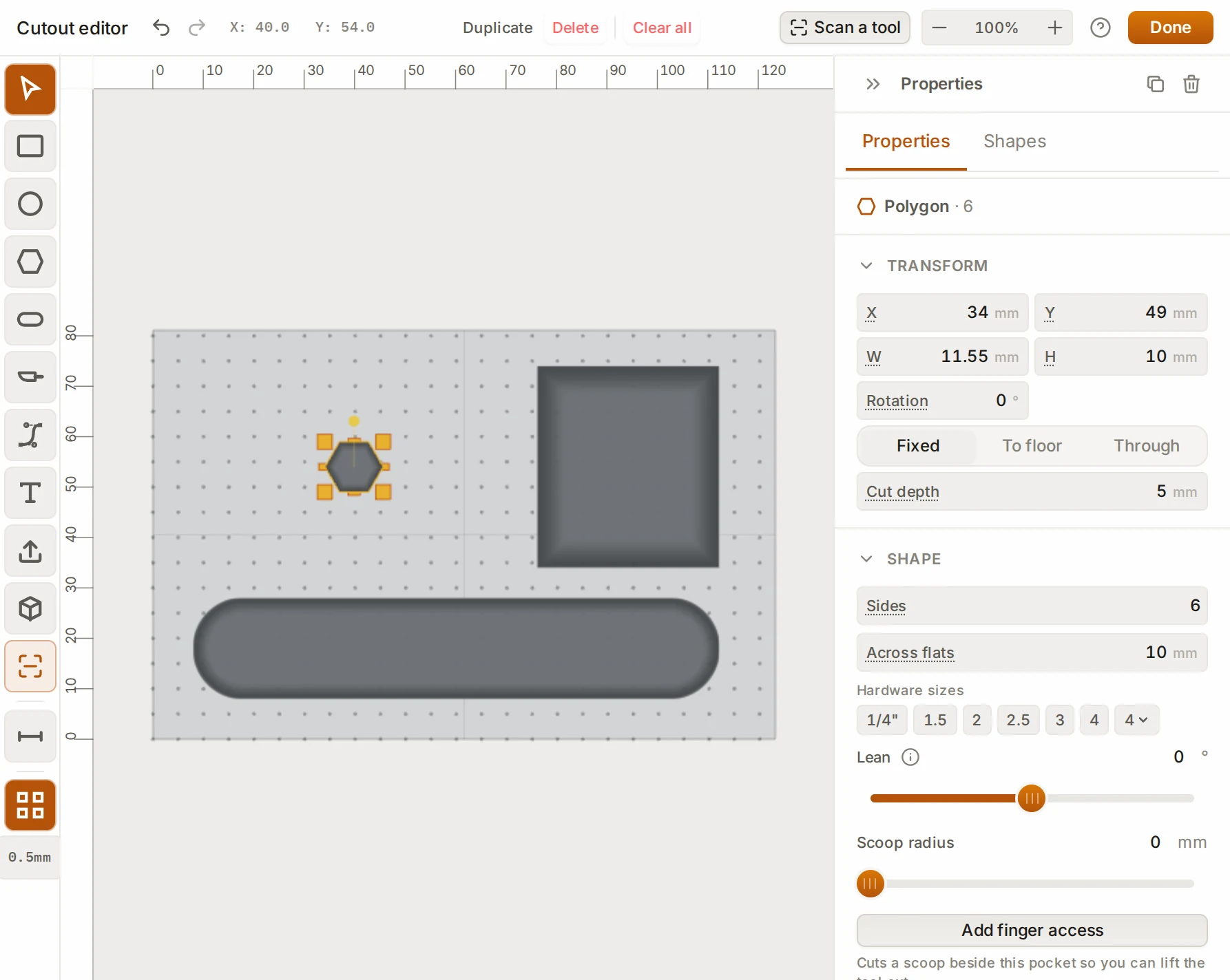
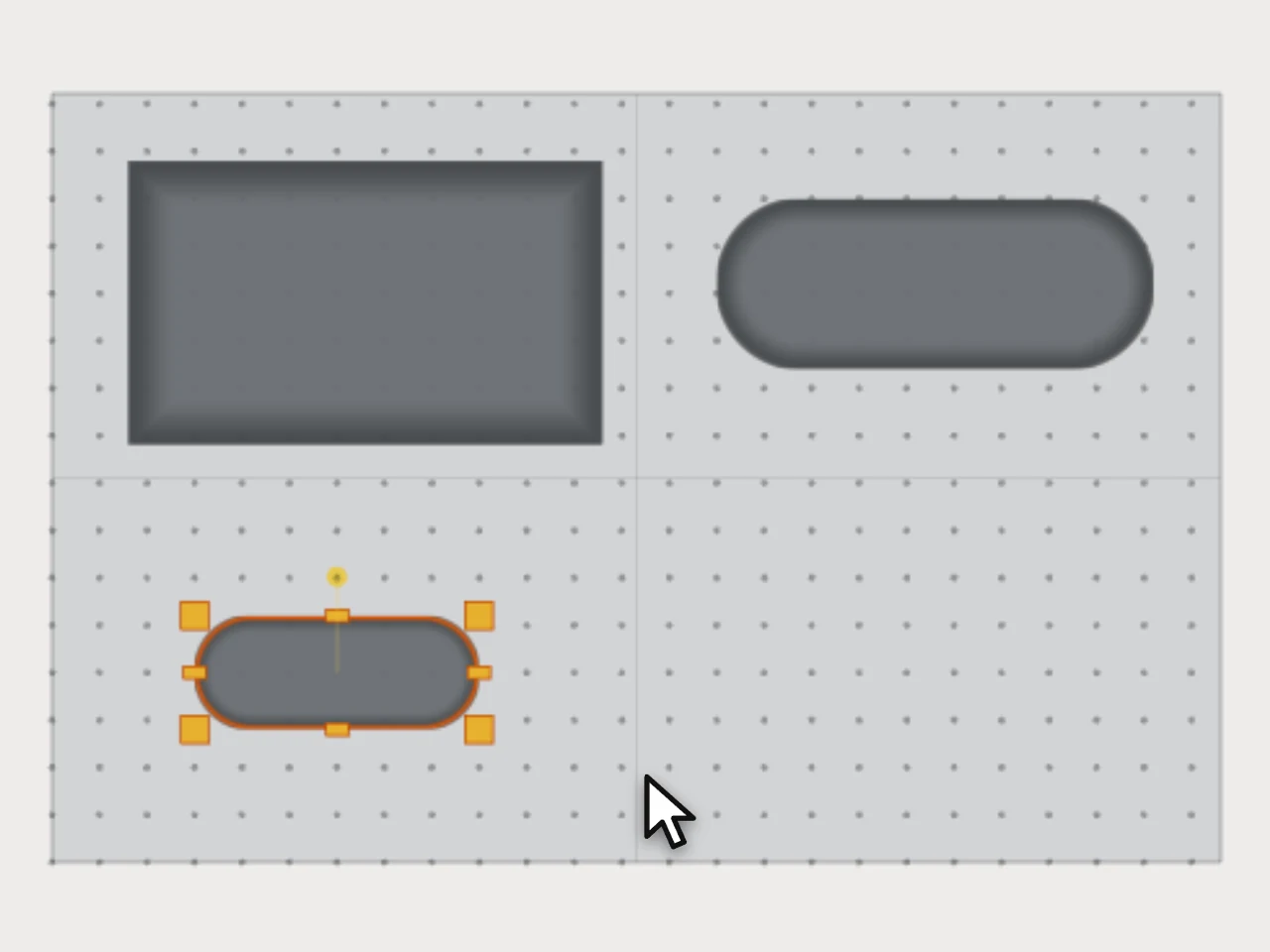
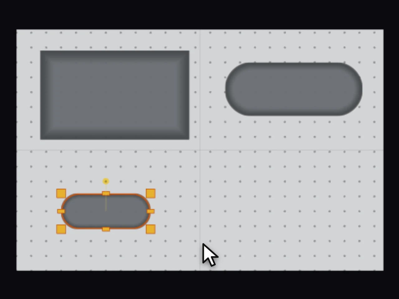
Pick a tool in the toolbar, then drag on the board. Hold Shift for a square or a true circle, and hold Alt to draw out from the center. Want a quick shape? Click without a drag, and you get a cutout of a standard size.
| Tool | Key | Use it for |
|---|---|---|
| Rectangle | R | Boxes and flat parts. |
| Circle | C | Round parts and socket drives. |
| Polygon | G | Hex bits and Allen keys. It has 3 to 12 sides, and starts with 6. |
| Slot | S | Tools that lie flat. The ends are fully round. |
| Knife slot | K | A blade slot for a knife block. |
| Pen | P | Any outline. Click to add a corner, or click and drag to add a curve. Click the first point to close the shape. |
| Text | T | A caption on the top. It cuts no cavity. |
Press V to go back to Select. While you draw with the pen, Ctrl+Z removes the last point and Esc stops the shape.
Set the size and position
Select a cutout and open Transform. Type the position, the width, the height and the Rotation. A typed size keeps the center of the cutout where it is. Positions start at the front-left corner of the inside of the bin.
Cutting for standard hardware? For a polygon or a circle, the Shape section shows Hardware sizes, such as a 1/4" hex bit or a 3/8" drive. A polygon size is Across flats, which is the size on a bit or Allen key specification.
To nudge a cutout, use the arrow keys: each press moves it 0.5 mm, or 5 mm with Shift. To line cutouts up on a grid, turn on Snap to grid in the toolbar.
Set the depth
A new cutout is 5 mm deep. Rectangles, circles, polygons, slots and pen shapes also have a Depth mode:
| Mode | What it does |
|---|---|
| Fixed | Cuts the Cut depth that you type, down from the top surface. |
| To floor | Keeps a set Floor of plastic under the cutout, measured from the bottom of the bin. The cutout gets deeper when you make the bin taller. |
| Through | Opens the cutout out of the bottom of the bin. |
A standard base counts toward the floor, so a To floor cutout never cuts into the base. Through isn't available in these cases:
- The cutout is in a group.
- The cutout has a lean.
- The cutout is beside a tapered wall.
- The bin has detachable feet.
Shape the top edge and the floor
Open Fit & insertion:
- Clearance adds room on each side so a part drops in. It goes from 0 to 5 mm.
- Entry edge sets the shape of the top edge. Chamfer is a 45° bevel that guides bits and sockets in. Round is a smooth curve for tools that you lift out by hand.
New circles, polygons, slots and pen shapes start with 0.2 mm of clearance and a small chamfer. Not sure? Keep that start, and print a fit test before the whole bin. A rectangle has no clearance setting: it cuts to the size that you set. To find the clearance that suits your printer, see Fit and tolerances.
To round the floor edges, set Scoop radius in Shape. On a rectangle, select Split to set each direction, and pick the edges that get the curve.
Lean a cutout off vertical
Lean tilts the cutout up to 45° in each direction, so an item slides in at a slope. The Rotation sets the direction of the tilt. The Layout Tool measures the depth along the tilt. Lean works on rectangles, circles, polygons, slots and pen shapes.
Open a cutout through a wall
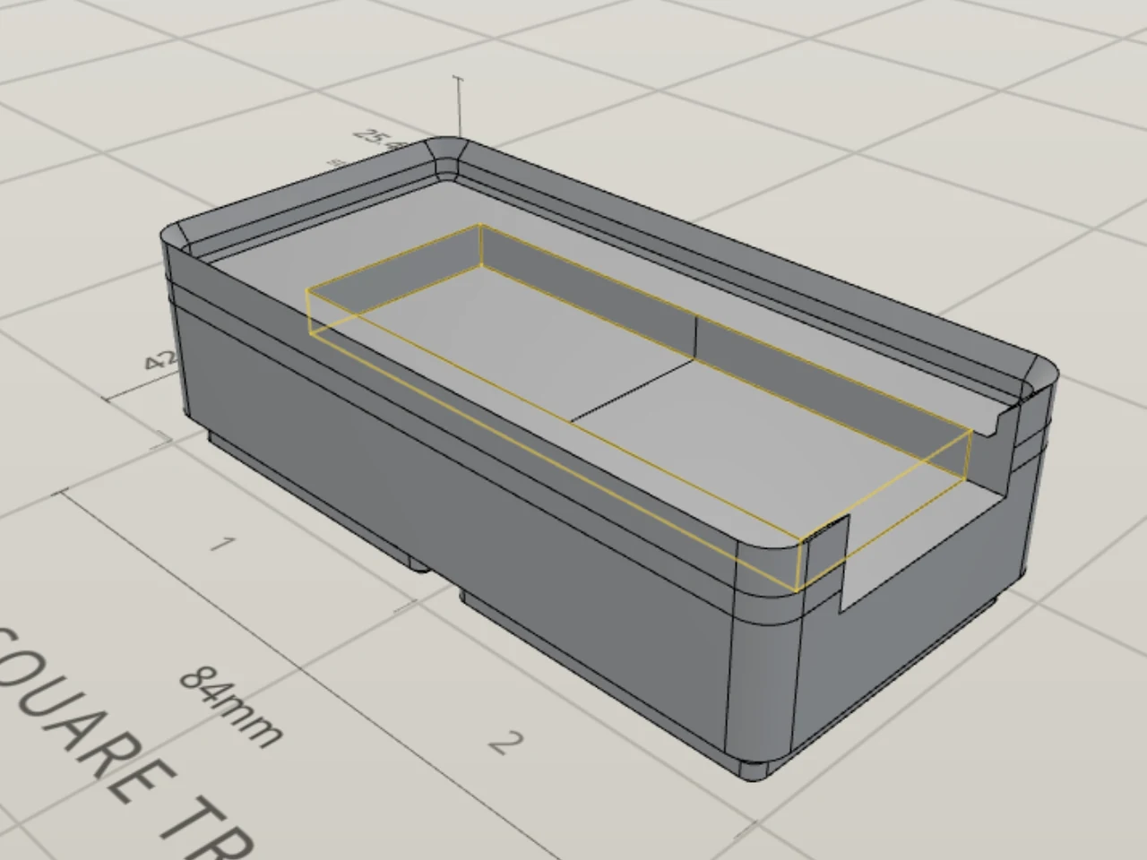
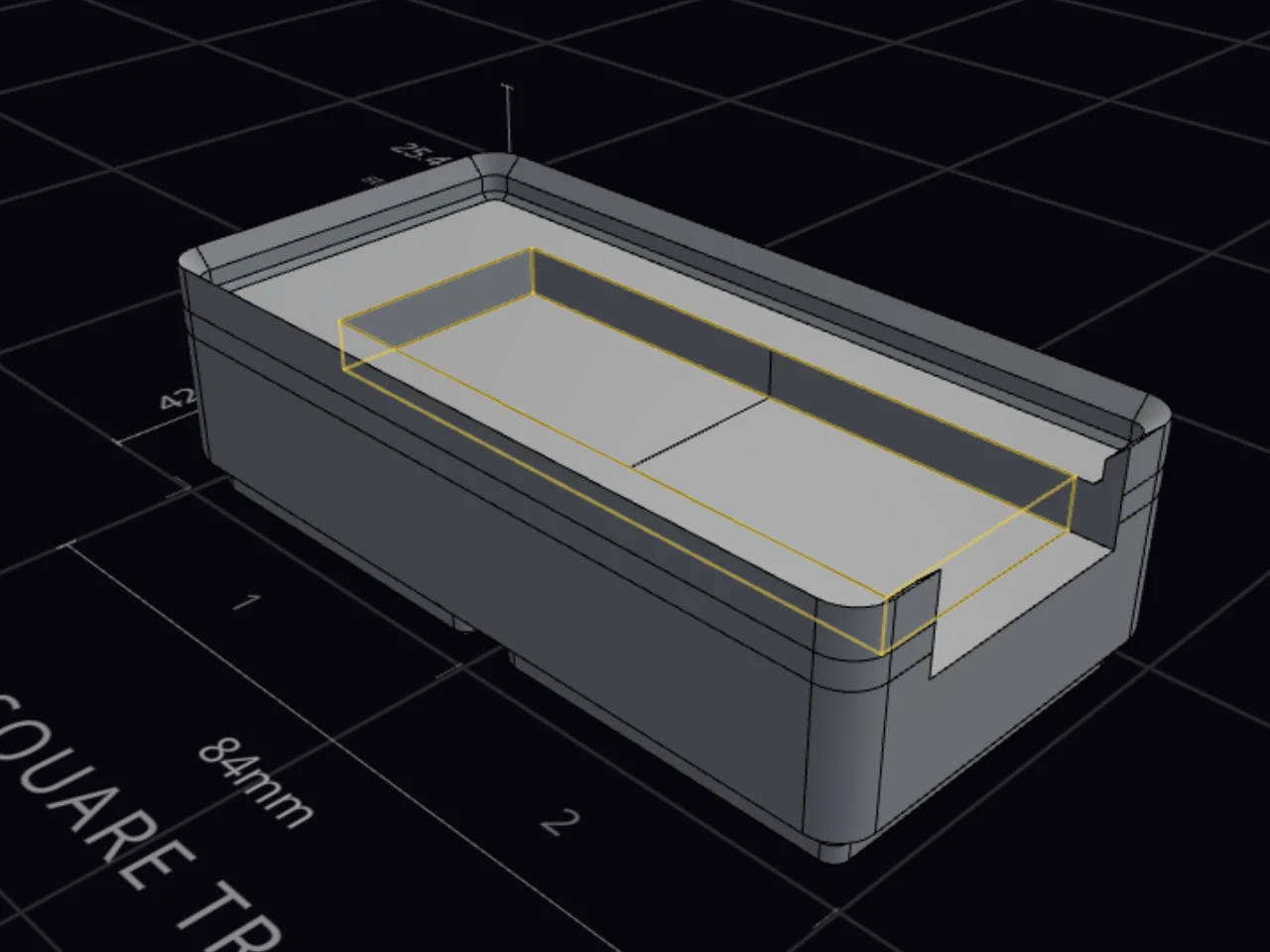
Need a ruler, a square or a tool handle to slide in from the side? Use Open through wall in Shape. Pick one or more walls. For each wall, set:
- Channel width: the width of the exit. It starts at the full width of the cutout.
- Opening: Open top cuts up through the rim. Tunnel keeps the wall and the stacking lip above the cutout.
A wall opening isn't available on a leaned cutout, in a repeated group, or on a tapered bin.
Cut one cutout to two depths
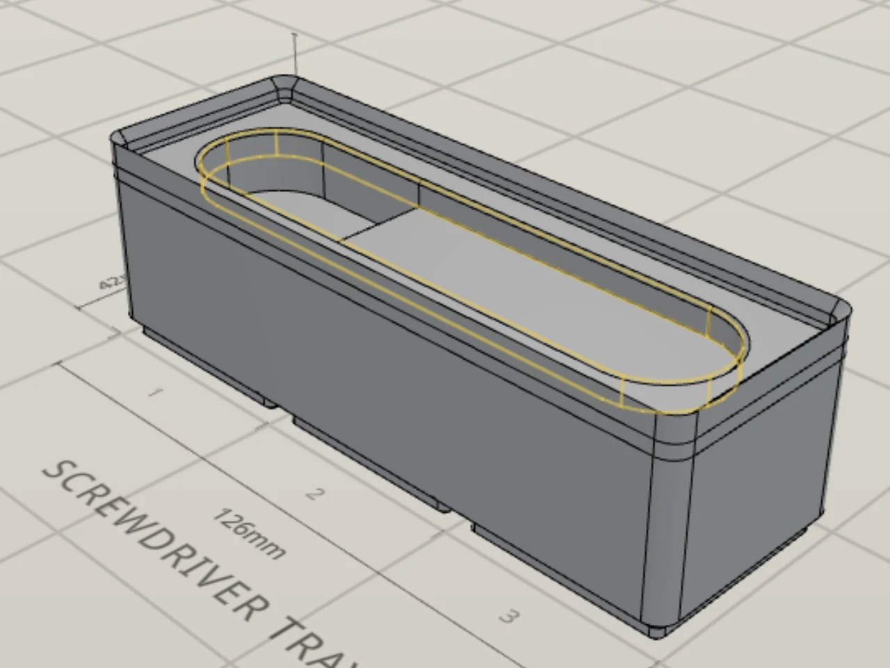
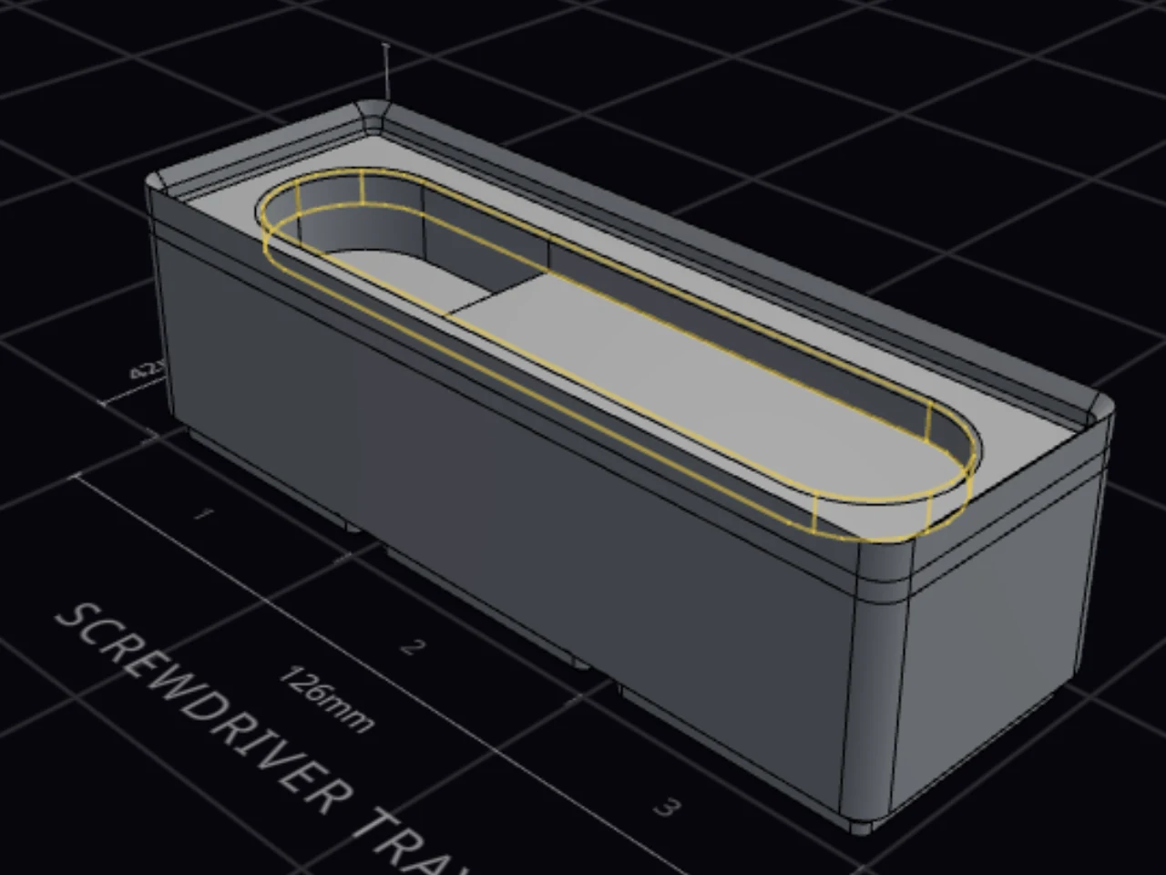
Some tools sit deeper at one end, such as a screwdriver with a thick handle. Give that end a deeper floor:
- Select the cutout.
- In Shape, click Split into two depths.
- Drag a line across the cutout on the board, from edge to edge.
- Set Side B depth.
Side A keeps the depth of the cutout. A split isn't available in a group, with a lean, or with a Through cut.
Add a label
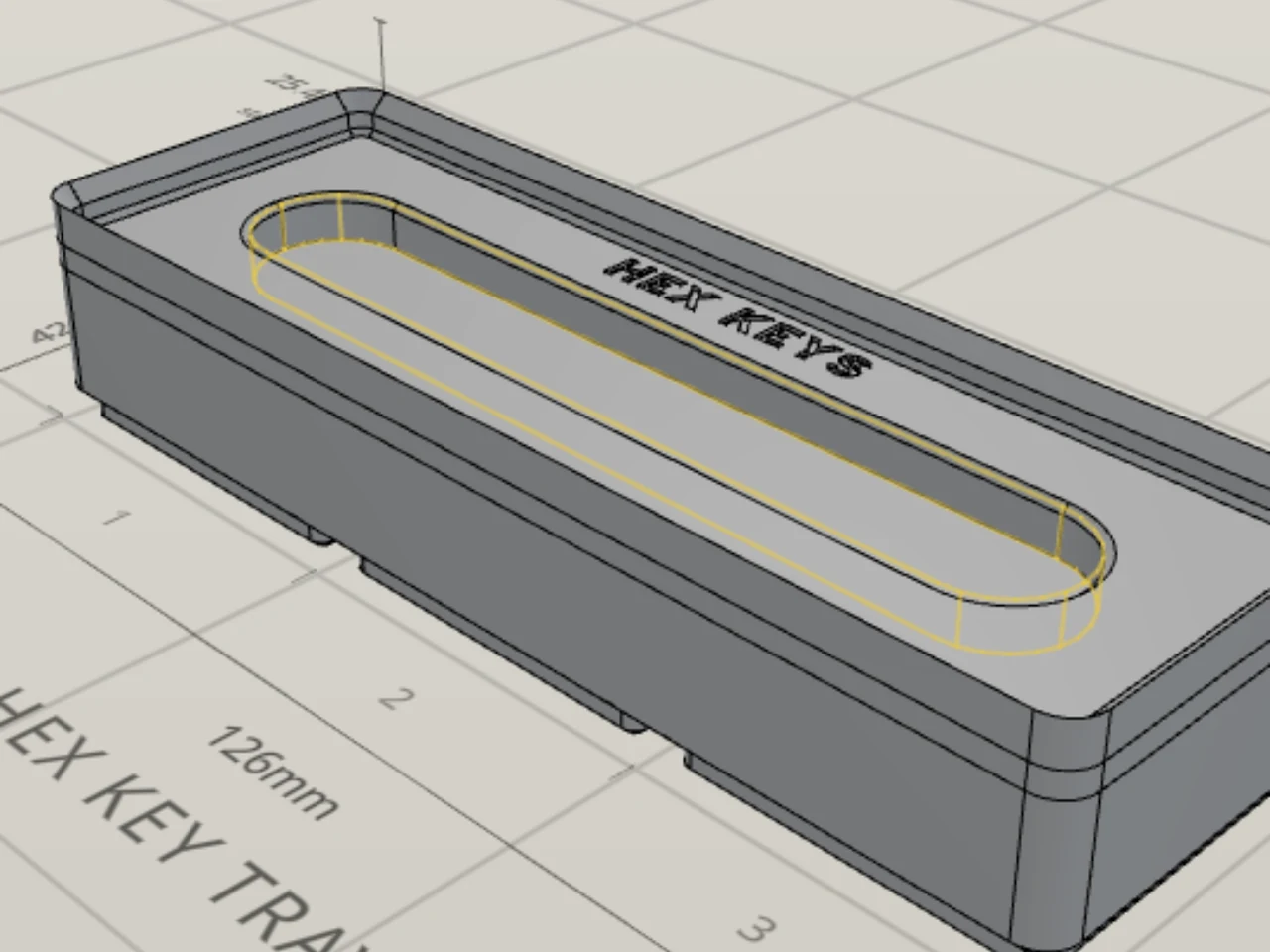
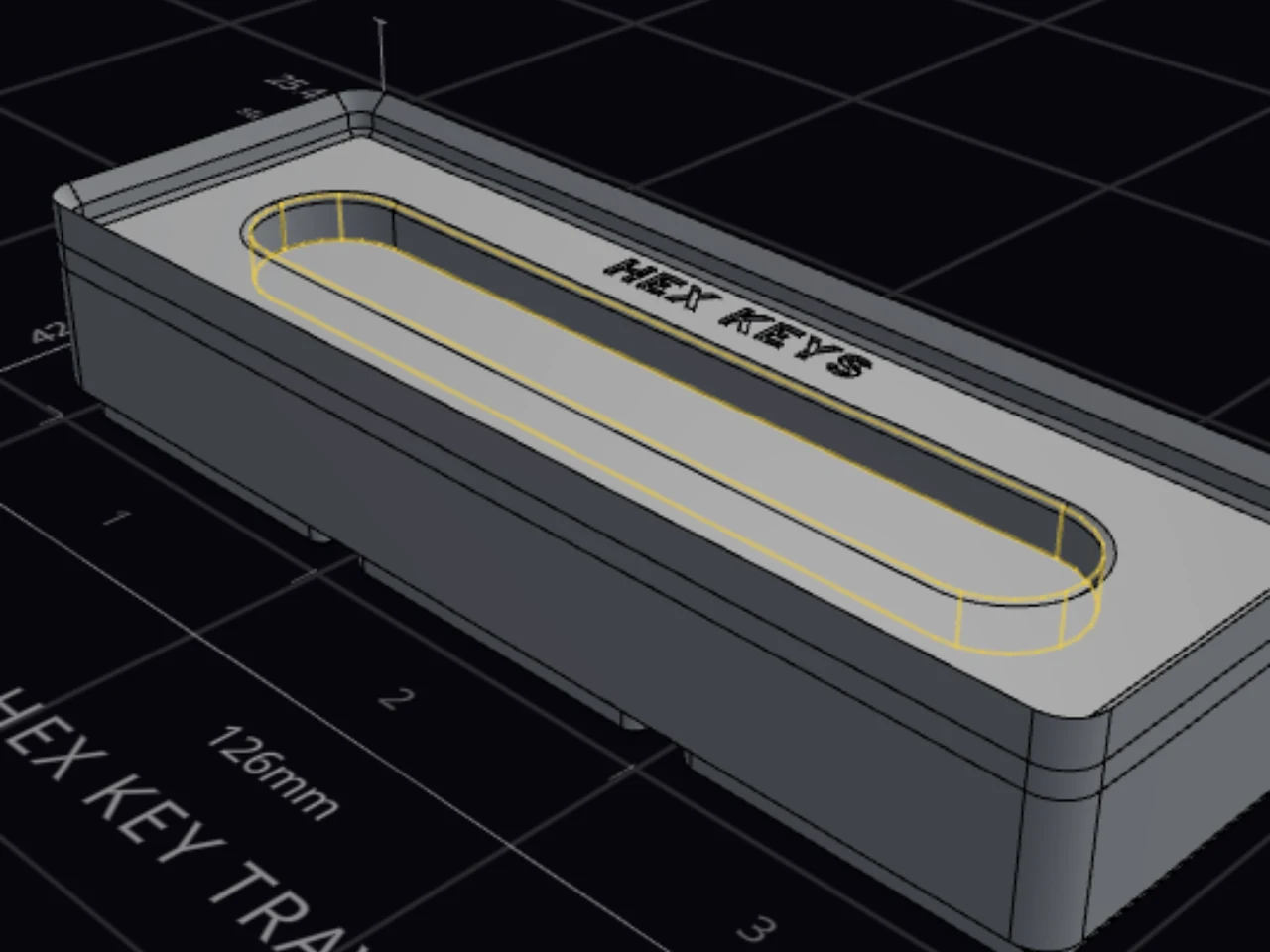
Open Label and type the text, up to 50 characters. To remove the label, clear the text. Then pick a Label type:
- Engrave cuts the text into the top, or raises it. The depth or height applies to all text in the design.
- Socket cuts a socket for a swappable label plate.
Label position puts the label above, below, beside or on the cutout. To move it more, drag the label on the board, or use Nudge X and Nudge Y.
When it goes wrong
The cut editor is gray and won't open
Read the line under Cut editor. It names the setting that blocks the cutouts. Is it a lightweight floor? Open Base, and set Lightweight mode to Underside. The bin stays light, and the cutouts come back.
A cutout cuts down into a solid floor. The inside lightweight mode hollows each foot from the inside, so no solid floor stays to cut into. A Spacer or a Base only bin has no room for cutouts at all.
You can't pick Through
Hover over the gray Through button to read why. Is the cutout in a group? Ungroup it with Ctrl+Shift+G. Does it lean? Set its Lean to 0.
A through cut opens out of the bottom of the bin, and some bins close that opening again. So the option is also off beside a tapered wall, with detachable feet, and on a Nesting body.
The cutout comes out shallower than you typed
Select the cutout and read the line under Cut depth. It gives the depth that the bin has room for. Lower the depth or the lean, move the cutout away from the edge, or make the bin taller.
A cutout can't go deeper than the plastic under the top surface. A lean also moves the floor of the cutout sideways, so it can meet a wall first. See Cutouts that are too deep.
Next steps
- Arrange cutouts: repeat, group, align and pack your cutouts.
- Import SVG and STL shapes: bring in a shape from another app.
- Check before you print: find thin walls and test the fit.
- Swappable label plates: print the plates for a socket label.
- Special bins: build a knife block with knife slots.