
Fit and tolerances
Each printer and each filament prints a little differently, so a part that fits on one printer can be tight on another. The Gridfinity Layout Tool lets you tune each part that must fit closely, and a small test print tells you the correct value. Here's what you can tune, and how to test it before you print a full drawer.
Test before you print a full drawer
Print one small bin and one small baseplate piece first. Put the bin in the plate, and make sure that it sits flat and lifts out freely. Then print the rest.
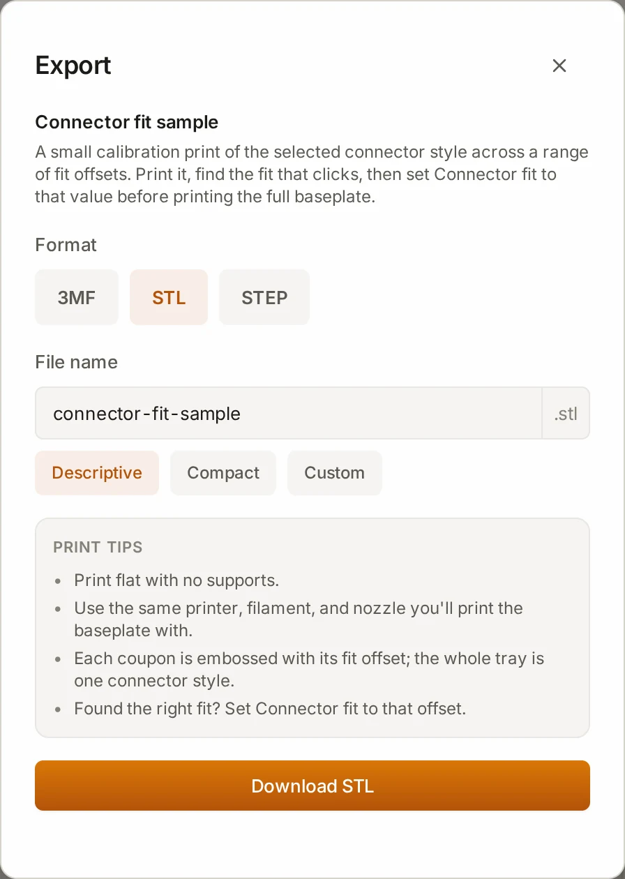
For each part that must fit closely, the Layout Tool also has a small test print. See Fit test prints below.
How a bin fits the plate
You don't need to tune this fit, because the Gridfinity standard sets it. Each pocket of the plate is 0.25 mm larger than the bin foot on each face, which gives 0.5 mm in total. The Layout Tool has no setting for this gap. It follows the open Gridfinity dimensions, so its bins and plates work with Gridfinity parts from other sources.
The bin and the plate must agree on the grid, though. The bin designer takes these values from the active layout, so a bin that you export fits that layout's plate:
- Grid unit
- Height unit
- Magnet anchor
- Low-profile base
Did you change one of these values? Then export the bins and the plate again. A low-profile bin still fits a standard plate, and a standard bin still fits a low-profile plate, with less grip.
Set your nozzle size
The nozzle size changes the parts that must fit closely, so that a wider nozzle can still print them. Set it in Settings, on the Print & material tab. The same Nozzle size field is also in the baseplate generator and below the bin list. In the bin designer, it's in Finishing. All of them change one value.
The range is 0.2 to 1.0 mm, and the default is 0.4 mm. Above 0.4 mm, the Layout Tool changes these parts:
- The keys and snap clips that join baseplate pieces
- The connectors and wall locks of a split bin
- The sockets that hold swappable label plates
At 0.4 mm, these parts keep their standard shape. The nozzle size doesn't change the walls of a bin. It does change the print time estimate. See Filament and time estimates.
Fit settings
| Setting | Where | What it changes |
|---|---|---|
| Tolerance | Baseplate generator, connectors | The gap of the connectors that join plate pieces, from −0.3 to +0.3 mm. Higher is looser. |
| Gap | Baseplate generator, stack | The air gap between stacked plates |
| Magnet diameter | Baseplate generator, underside magnets | The hole size. Add 0.2 to 0.5 mm to the magnet diameter. |
| Crush ribs | Baseplate generator, magnet holes. Bin designer, Base | Ridges that grip a magnet with no glue |
| Clearance | Bin designer, cutout editor, each cutout | The extra size of a cutout, so that the part drops in |
| Fit tolerance | Bin designer, Interior, removable dividers | The fit of the dividers in their slots |
| Pin size | Bin designer, Base, detachable feet | The fit of each foot on its pin. A smaller pin gives a looser fit. |
| Plate fit offset | Bin designer, Interior, label tab sockets | The fit of a label plate in its socket. Negative is tighter. |
| Hinge fit | Bin designer, Lid, hinged lid | The gap between the hinge and the pin |
| Sliding clearance | Bin designer, Lid, sliding lid | The gap between the lid and its channel |
For a hinge or a sliding lid, raise the value if the part binds, and lower it if the part rattles.
Fit test prints
A test print is small and cheap, so print one before you guess at a value.
| Test | Where to find it | What you get |
|---|---|---|
| Connector fit | Print fit test under the connector settings | One coupon for each fit value, with the value on the surface |
| Stack fit | Print fit test in the stack settings | A stack of two 1 by 1 plates, to tune the gap |
| Cutout fit | Print fit test in the cutout editor | A thin slice of the bin top with every cutout, or a thin ring around each cutout |
| Label plate fit | Print fit test in the label tab settings, in Interior | Five sockets from −0.10 to +0.10 mm, and one blank plate |
Print each test with the same printer, filament, nozzle and settings as the real part. Print it flat, with no supports. Then set the fit setting to the value of the test part that fits best. Print a fit test shows the cutout test step by step.
When a connector key is too tight
The print guide of a split baseplate gives these tips for a Puzzle key or a Snap clip:
- Use a 0.4 mm nozzle. A larger nozzle loses the detail of the key.
- In your slicer, set the initial layer horizontal expansion to about −0.1 to −0.2 mm. First-layer squish is the most frequent cause of a tight key.
- Print the key flat, with 2 or more walls.
- Does the key not go in? Raise Tolerance. Is it loose? Lower it.
Next steps
- Split for your print bed: choose a connector style for plate pieces.
- Check before you print: find thin walls and merged cutouts before you print.
- Troubleshooting prints: solve a bin that is too tight in the plate.