
Workshop
Some tools store best standing up or hanging, and a flat cutout can't do that. Workshop builds a tool holder out of 3D parts on a Gridfinity base: posts, fins, tubes, cradles, racks and more. It carries an experimental label.
This page also shows how to export a shadow board from the cutout editor.
Start a Workshop build
- Open the bin designer.
- Open your saved designs:
- On a computer, click the icon button next to the design name. Its tooltip reads Open design list. On a wide screen, the button also reads Designs.
- On a tablet or a phone, tap the design name in the header.
- In Saved designs, click New Workshop build (experimental).
- If you changed the open design, a box asks you to start a new design. Click New design. Your current design stays in your saved designs.
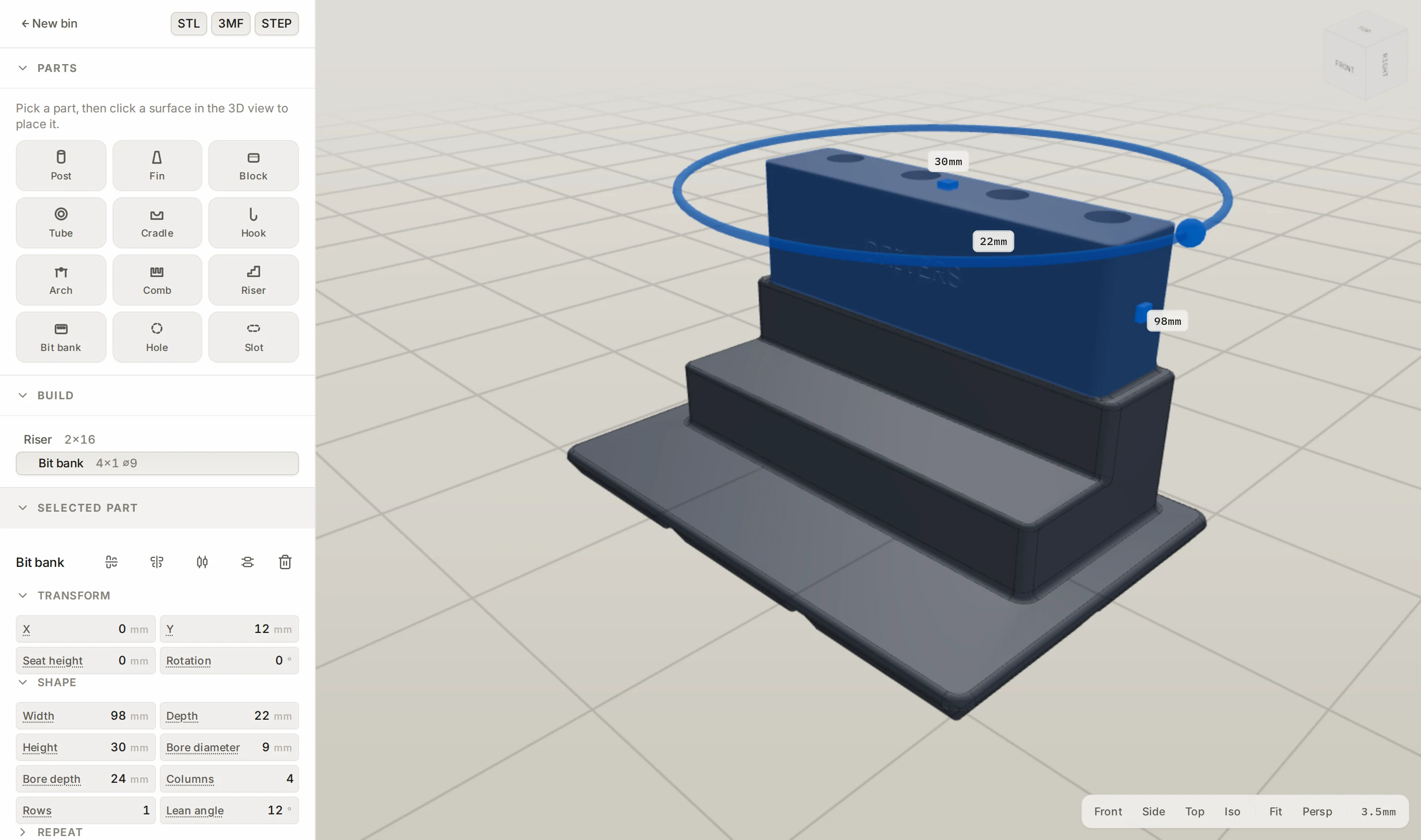
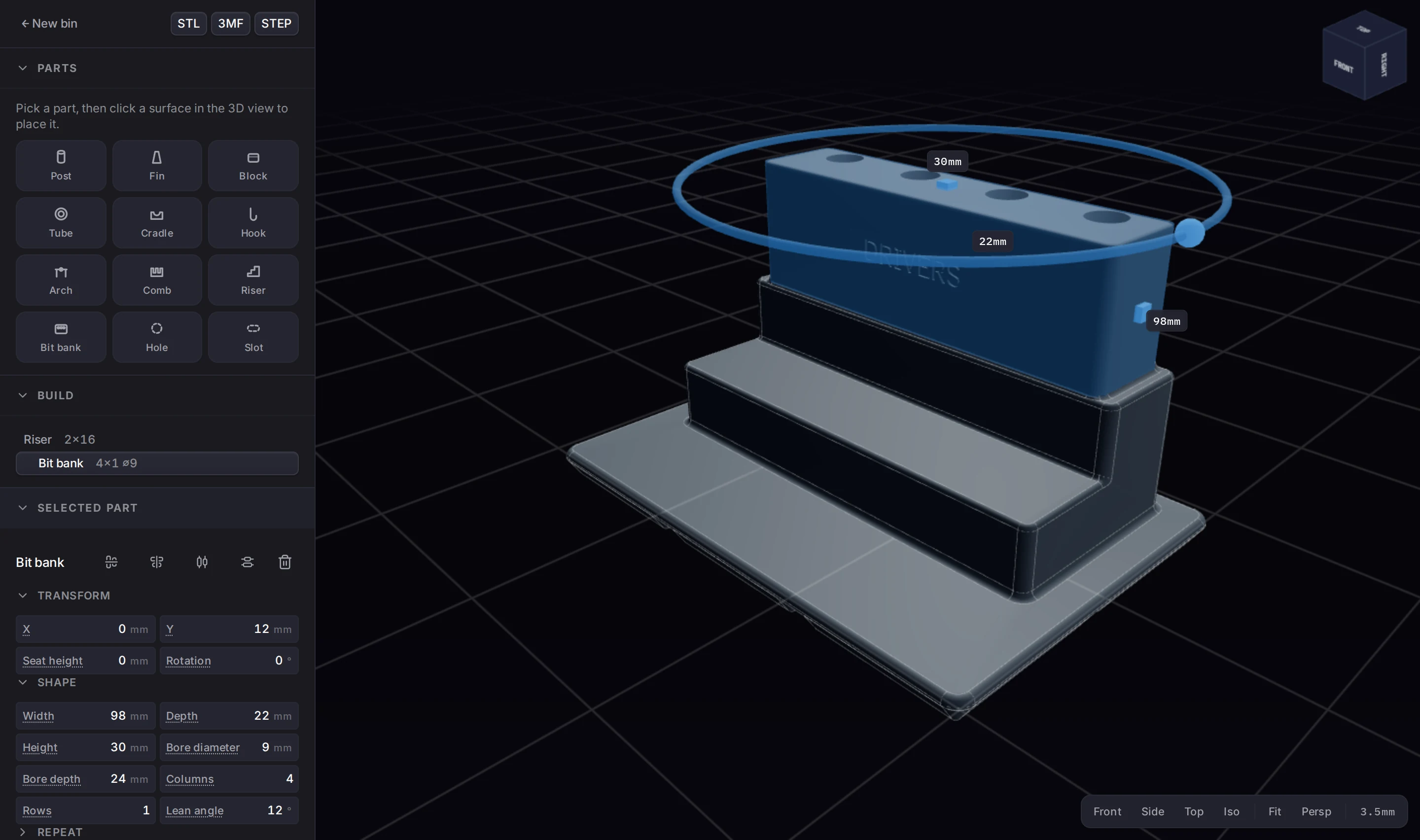
The panel on the left holds the parts, the build tree and the base settings. The 3D view on the right is where you place the parts. A build saves to your saved designs like a bin, and you can link it to a bin in a layout.
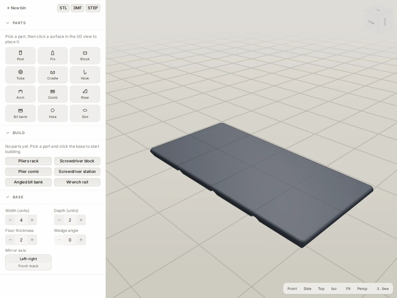
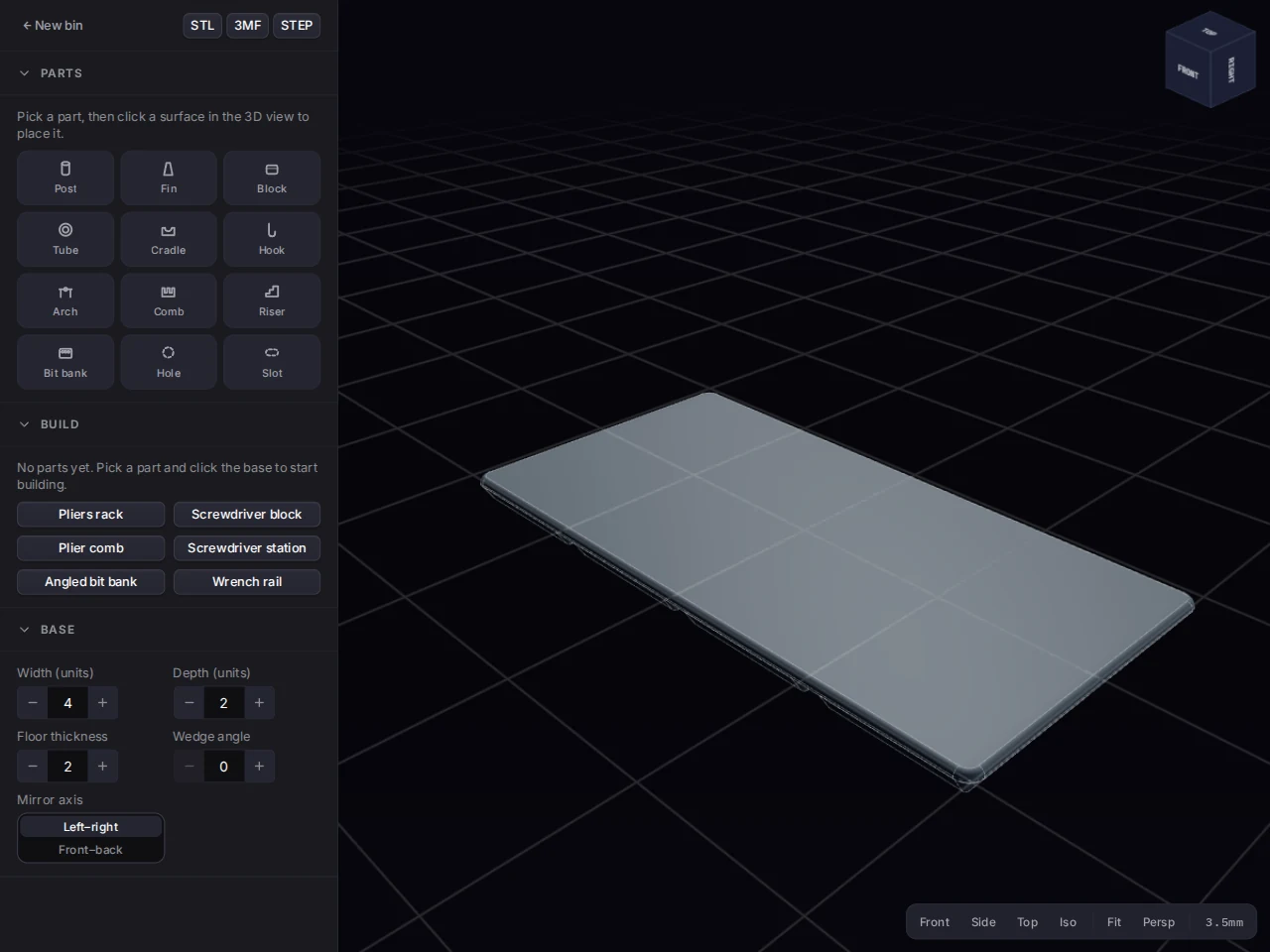
Not sure what to build first? When the build is empty, the Build section offers templates to start from:
- Pliers rack
- Screwdriver block
- Plier comb
- Screwdriver station
- Angled bit bank
- Wrench rail
Set up the base
Under Base, set the Width (units) and the Depth (units) in grid units, and the Floor thickness. Want the top of the base to tilt? Set a Wedge angle and pick the Low edge.
Place parts
- In Parts, click a part.
- Click a surface in the 3D view to place it there.
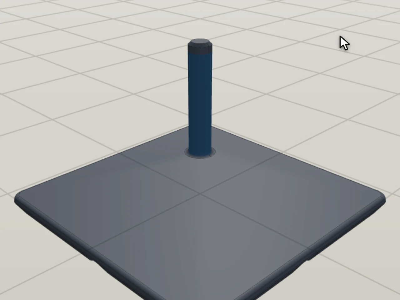
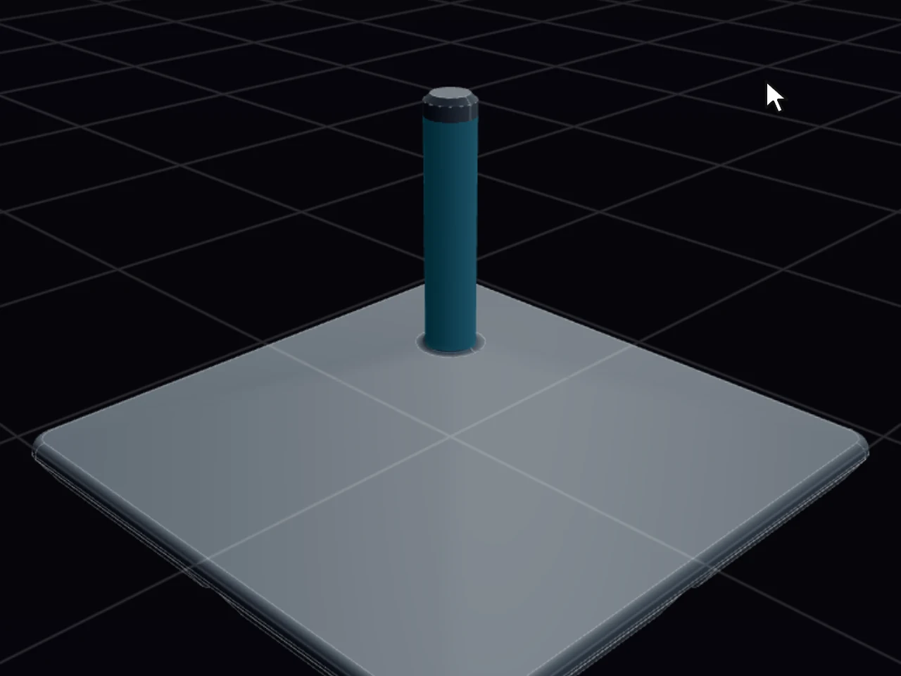
You can place a part on the base or on top of another part. The Build section shows which part sits on which.
| Parts | Use |
|---|---|
| Post, Fin, Block, Tube | Simple shapes that stand on the base. |
| Cradle, Hook, Arch | Parts that hold or carry a tool. |
| Comb, Riser, Bit bank | Rows of slots, steps or holes. |
| Hole, Slot | Cutters. They remove material from the parts below them. |
A cutter has a Cutout profile. Pick a Circle, a Rectangle, a Polygon or a Slot. To cut the outline of a real tool, click Scan with phone…. See Scan with your phone.
Select parts
- Click a part to select it.
- Shift+click a part to add it to the selection or to remove it.
- Hold Shift and drag over empty space to select all the parts in a box.
With two or more parts selected, a toolbar opens at the top of the 3D view:
- Align X and Align Y line the parts up.
- Distribute X and Distribute Y space them evenly.
- Duplicate, Delete and Clear selection work on the whole selection.
Right-click a part for Duplicate, Rotate 90°, Mirror and Delete.
Move, turn and resize parts
- Drag a part to move it. Drop it over another part to put it on top of that part.
- Drag the ring around the selection to turn it. Several parts turn together around their center.
- Drag a handle on one selected part to change its size in that direction. For an exact value, click the number beside a handle and type it.
To move several parts, drag one of the selected parts, and the others come along. Resize handles show only when you select one part. Each drag is one step for undo, so one undo takes back a wrong move.
The Selected part section gives exact values for the position, the Rotation, the Seat height and the size of the part.
Part warnings
The inspector warns you when a part has a problem:
- Floats above its seat
- Extends past the base
- Overhang may need supports
- Cuts into the socket
- Hangs off its parent
Look at the build
- The buttons in the corner of the 3D view set the camera: Front, Side, Top or Iso.
- Fit (F) zooms to the selection.
- P changes between Persp and Ortho.
Export the build
When the build looks right, click STL, 3MF or STEP at the top of the panel.
Export a shadow board
A shadow board is a flat outline of a bin top. Use it to cut a matching board, a foam insert or a drawer liner on a laser cutter or a CNC machine. This export lives in the cutout editor of a bin with Custom cutouts, not in Workshop.
- Open the cutout editor. See Cutout basics.
- In the Properties tab, click Export shadow board.
- Pick SVG or DXF. To make each opening larger by its clearance, tick Include each pocket's clearance.
- Click the download button.
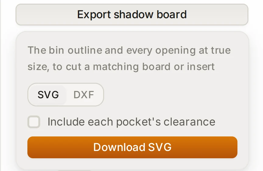
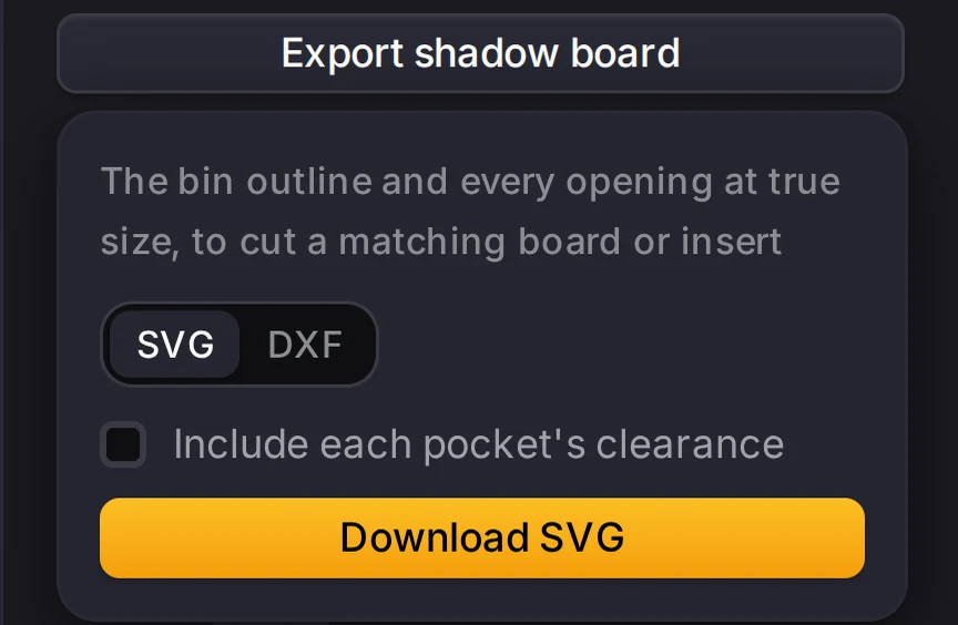
The file has the outline of the bin and every opening at true size. It includes each copy of a repeat, the result of each group, STL imprints, and openings through a wall. Cutouts that overlap become one opening. Entry edges, depths and leans have no outline.
When it goes wrong
The part warnings in Workshop are advice. None of them stops an export, so read them before you print.
A part floats above its seat
Set Seat height to 0. Or drag the part onto the base or onto another part.
A part with a seat height above 0 has nothing under it, so it would print in mid-air.
A part hangs off its parent or past the base
Drag the part back. Its center must sit on the top of the part below it, and all of it must stay on the base.
A part that sits on another part stands on that part's top face. Past that face, or past the edge of the base, the part has no support.
A hole or slot cuts into the socket
Lower the Cut depth of that cutter, or raise the Floor thickness of the base.
A cutter that goes below the floor cuts into the Gridfinity feet under the base, the part that sits in the baseplate.
A part may need supports
Make the overhang smaller, or turn on supports in your slicer. The warning shows above these values:
| Part | Value |
|---|---|
| Block | A Wedge angle of 45° |
| Arch | A Span of 80 mm |
| Hook | A Reach of 40 mm |
Next steps
- Cutout basics: cut tool shapes into a solid bin.
- Saved designs and linked bins: find and reuse your Workshop builds.
- Place and edit bins: put a build in a drawer layout.